How to Build a Model Onager
By Dyderich Wolfhart
An Onager is what most people think of when they are talking about a catapult. The following is a step by step process to make a working model of one of these siege engines.
Caution Caution Caution Caution
Although this looks like a toy it does actually hurl a projectile. Never use a hard projectile or shoot at another person. Improper use could result in injury.
You need the following list of materials:
| Wood: | 1” x 2” x 6’ (note: although the lumber yard may sell it as 1 x 2, it’s closer to ¾” x 1 ½”) |
| 4” x 4” x ¾” Plywood | |
| Wooden Dowel rod: | ¼” x 12” |
| 3/8” x 6” | |
| Metal rod: | 1/8” x 9” |
| Rope: | ¼” x22” |
| Metal flat washers: | 3/8” – qty: 2 |
| Wood Glue | |
| Foam Rubber(old mouse pads work great) | 1” x 1” |
You will need the following tools:
Ball peen hammer
Wood saw
Drill (drill press preferred)
¼” drill bit
½” drill bit
3/8” drill bit
9/64” drill bit
1¼” countersink wood bit
3” hole saw
Miter box
Slip joint pliers or wood clamp
Hacksaw (or other metal cutting saw)
Cutting the wood:
The first thing you must do is cut your 1 ½” x ¾” wood to the following lengths:

Cut the ¼” dowel into twelve 1” pieces.
Cut the 1/8” steel rod into two 3” long pieces and two 1 ½” pieces.
Cut the 3/8” wooden dowel rod into one 6” piece
The next step is to cut the 45°angles on the supports for the uprights.
Using a miter box, make cuts as illustrated in the above diagram. Use the two 4 7/8” pieces of wood you cut earlier.
Drilling the holes:
With the exception of the ½” and the 9/64” hole, all drilling will be to only ½” deep.
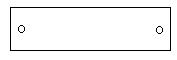
Except as noted above all the holes are drilled with the ¼” drill bit. The ¼” holes should only be ½” deep. The holes on the very ends are 5/16” from the ends. All holes are centered on the wood. You then repeat the process with the other 12” piece except that the holes near the ends are drilled on the opposite side, so that when the two pieces are laid side by side the end holes face inward. Like the diagram below.
Next take the two 6” pieces. Drill holes in the very center of the ends as shown below. Flip them over and repeat on the other end.

On the 7 3/8” piece measure and drill holes 5/16” in from the ends and centered as shown.
Next take the two 3 5/8” pieces and drill the holes as shown below.
Again all these holes are drilled using the ¼” drill bit and are only ½” deep.
Take your upright supports and drill in the very center of the cut edges. You can easily find the center by lining up the corners with a straight edge and marking a line. Repeat the process with the other corners and where the two lines meet is the center. Be very careful. You want the holes to be perpendicular to the cut ends as show below.
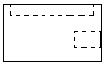
Lastly take the 4”x 4”x ¾” piece of plywood and drill out the center with your 3” hole saw. Next, take the 3” round piece you just made and drill a 3/8” hole centered on one edge.
On the side use the 1 ¼” countersink bit to make a ¼” indentation as illustrated below:(WARNING: use either a wood clamp or pliers to hold while drilling)
Making the locking mechanism:
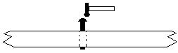
Take one of the 12” long pieces and insert a 1 ½” long piece of 1/8” steel rod into the 9/64” hole.
Place on a hard solid surface and mushroom out the end of steel so that it can no longer pass through the hole. Flip over and repeat on the other side. The rod should now be able to slide freely back and forth but not pass through the hole.
To mushroom out the end of the steel rod gently tap around the outside edge repeatedly until it mushrooms out.
Assembly:
In the following instructions, you will attach the pieces together using the ¼” x 1” wooden dowels. Place a drop of glue in each hole before placing the dowel in the hole.
Step 1:
Attach the upright supports to the uprights as shown below.
(note: insure that the upright are attached to the lower of the two holes drilled on the sides.)
Step 2:
Now attach the above pieces to the two 12” pieces as shown below.
Step 3:
Connect the above pieces together by using the two 6” pieces with the holes in the ends. They attach at the holes in each end of the 12” pieces. The last piece attaches to the front top of the upright supports. When complete your model should now look like this from above:
Glue a small piece of foam rubber in the middle of the cross piece. This will keep your throwing arm from breaking.
Insert the 3/8” wooden dowel into the 3” disk you cut and drilled. This will be the throwing arm.

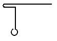
Step 4: making the spring levers
Take the two 3” pieces of 1/8” steel rod and bend to a 90° angle ¾” in from the ends using a pair of pliers. When you are done they should look like this:
![]()
![]() (note: There may be sharp burs on the tips. Remove with file to prevent injury.)
(note: There may be sharp burs on the tips. Remove with file to prevent injury.)
Step 5: constructing the spring
Tie the ends of the rope together using a square knot as close to the end as possible. Thread the rope through the ½” holes so that the loops stick out both sides. Place a 3/8” flat washer over the loop followed by a spring lever to prevent the rope from slipping back through the hole. Repeat on the other side. Now insert the small end of the throwing arm in between the ropes centered between the sides as shown:
Congratulations!
Your Onager is complete. To operate turn the spring levers. Rotate both levers forward so that throwing arm is forced against the stop. Be sure to keep the tension even on both sides. When the rope is tight enough, slide the locking mechanism out on both sides to keep the rope from loosening. WARNING: if the sides start to bow, STOP tightening. You can over tighten the spring and snap the wood. You can also flip the spring levers sideways so they don’t stick out. To prolong the life of the rope loosen the spring when not in use. To fire your Onager, simply pull back the throwing arm, load with a soft projectile, and let fly.
HAVE FUN and BE SAFE!
Appendix A:
If you wish, you can create a firing mechanism out of a paper clip and a small screw.
This is accomplished by bending a paperclip as show below:
Using the small screw, attach to end of the Onager that the throwing arm touches when it is pulled back. The short doubled over end should be long enough to slip over the shaft of the throwing arm. To load pull back the throwing arm and slip the short part over the arm, load soft projectile, and fire by pushing down on the long section.